Brief introduction
Series S Pumps are a single stage, double suction and axially split centrifugal pump and are used to pump clean water or Similar liquids in physical cal and chemical properties. The temperature of the pumped liquid should not be exceeded 80℃. And The pump is mainly suitable for water supply in factories, mines, cities, hydropower stations, various conservancy projects and irrigation in farms,ets.
Construction description
The inlet and outet of the pump are both under the centreline of the pump shaft, they are vertical to the shaft centreline andgo to horizental direction. You needn't dismount the outlet and inlet pipes for inspection. Looking from the driven direction therotaty direction is clockwise(Or can change to counterwise as user's requirement).
Main parts of the pump:(1)Pump casing (2)Pump cover (3)Impeller (4)Shaft (5)Double suction seal ring (6)Shaft sleeve, etc. They are made of cast iron except the shaft material being made of fine steel.
The impeller working house is composed of pump casing and pump cover. The threaded holes for installing the vacuum gauge and manometer are separately located at the suction flange and the discharge flange. At the bottom of the inlet or outlet flange a drain threaded hole equiped here.
The impeller checked by statical equilibrium is fixed on the shaft by the shaft sleeves and the shaft nuts, which axial position can be adjusted by the sleeve nuts. And for the axial force of the impeller, it can be adjusted by using the symmtrical distribution of the impeller and the balance of the two sides water.
The pump shaft is supported by two single redial ball beatings.
The bearing fitted on the ends of the pump casing is installed in the bearing body and is lubricated by oil grease.
The double suction seal ring is used to reduce the leaking water from the pressure water house which would flow back to the suction water house.
The pump is driven by the moto though the flexible coupling(It also can be driven by diesel engine if it is necessary)
The shaft seal is soft stuff. The packing ring is installed among the packings in order to prevent air from coming into the pump and cooling lubricating sealing case, and while the pump working, it is allowed to let a little high-pressure-water going through the trapeziform concave groove on the horzontally split face of the pump cover and flow into the packing case, function as wate seal(Mechanical seal is available as the customer's requirement.)
S型单级双吸离心泵中开式
型号Model
流量(m³ /h)
扬程(m)
电机功率(KW)
转速(r/min)
100S90
60
80
95
95
90
84
37
2950
100S90A
50
72
86
78
75
70
30
2950
150S10
78
130
156
12.5
10
8.5
7.5
1450
150S14
120
200
240
19.5
14
9.5
11
1450
150S18
96
160
192
23
18
15.5
15
1450
150S100
126
160
202
102
100
93
75
2950
150S78
126
160
198
82
78
70
55
2950
150S78A
112
144
180
67
62
55
45
2950
150S50
132
160
220
52
50
40
37
2950
150S50A
112
144
180
44
40
35
30
2950
150S50B
108
133
160
38
36
32
22
2950
200S95
183
280
324
103
95
87
110
2950
200S95A
198
270
310
82
75
68
90
2950
200S63
216
280
351
69
63
53
75
2950
200S63A
180
270
324
54.5
46
37.5
55
2950
200S42
216
280
342
48
42
35
45
2950
200S42A
198
270
310
43
36
31
37
2950
250S28
192
320
384
29.5
28
26.5
37
1450
250S65
360
485
612
71
65
58
132
1450
250S65A
342
468
540
61
54
50
110
1450
250S39
360
485
612
42.5
39
32
75
1450
250S39A
324
468
576
35.5
30.5
25
55
1450
250S24
360
485
576
27
24
19
45
1450
250S24A
342
414
482
22.2
20.3
17.4
37
1450
250S14
360
485
576
16
14
11
30
1450
250S14A
320
432
504
13.7
11
8.6
18.5
1450
300S110
590
790
936
113
110
105
440
1450
300S90
590
790
936
93
90
82
315
1450
300S90A
576
756
918
86
78
70
280
1450
S型单级双吸离心泵中开式
型号Model
流量(m³ /h)
扬程(m)
电机功率(KW)
转速(r/min)
300S90B
540
720
900
72
67
57
220
1450
300S58
576
790
972
63
58
50
180
1450
300S58A
529
720
893
53
49
42
160
1450
300S58B
504
684
835
46
43
37
132
1450
300S32
612
790
900
36
32
28
110
1450
30032A
551
720
810
31
26
24
75
1450
300S19
612
790
935
22
19
16
55
1450
300S19A
504
720
829
20
16
13
45
1450
300S12
612
790
900
14.5
12
10
37
1450
300S12A
522
684
792
11.8
10
8.7
30
1450
350S125
850
1260
1660
140
125
100
710
1450
350S125A
803
1181
1570
125
112
90
63
1450
350S125B
745
1098
1458
108
96
77
500
1450
350S75
972
1260
1440
80
75
65
355
1450
350S75A
900
1170
1332
70
65
56
280
1450
350S75B
828
1080
1224
59
55
47.5
220
1450
350S44
972
1260
1476
50
44
37
220
1450
350S44A
864
1116
1332
41
36
30
160
1450
350S26
972
1260
1440
30
26
22
132
1450
350S26A
864
1116
1296
26
21.5
16.5
90
1450
350S16
972
1260
1440
20
16
13.4
75
1450
350S16A
864
1044
1260
16
13.4
10
55
1450
500S98
1620
2020
2340
114
98
79
800
970
500S98A
1500
1872
2170
96
83
67
630
970
500S98B
1400
1746
2020
86
74
59
560
970
500S59
1620
2020
2340
68
59
47
450
970
500S59A
1500
1870
2170
57
49
39
400
970
500S59B
1400
1746
2020
46
40
32
315
970
500S35
1620
2020
2340
40
35
28
280
970
S型单级双吸离心泵中开式
型号Model
流量(m³ /h)
扬程(m)
电机功率(KW)
转速(r/min)
500S35A
1400
1746
2020
31
27
21
220
970
500S22
1620
2020
2340
24.5
22
19.4
185
970
500S22A
1400
1746
2020
20
17
14
132
970
500S13
1620
2020
2340
15
13
10.4
110
970
600S75
3170
75
800
970
500S75A
2880
65
630
970
600S47
2500
3170
3500
56
47
38
560
970
600S32
2520
3170
3960
37
32
22
400
970
600S32A
2304
2880
3600
31.5
27
20
280
970
600S22
3170
22
280
970
600S22A
2880
18.2
200
970
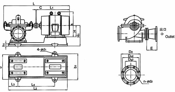
安装指导图(带底座): The drawing for the installation dimensions (with bedplate):
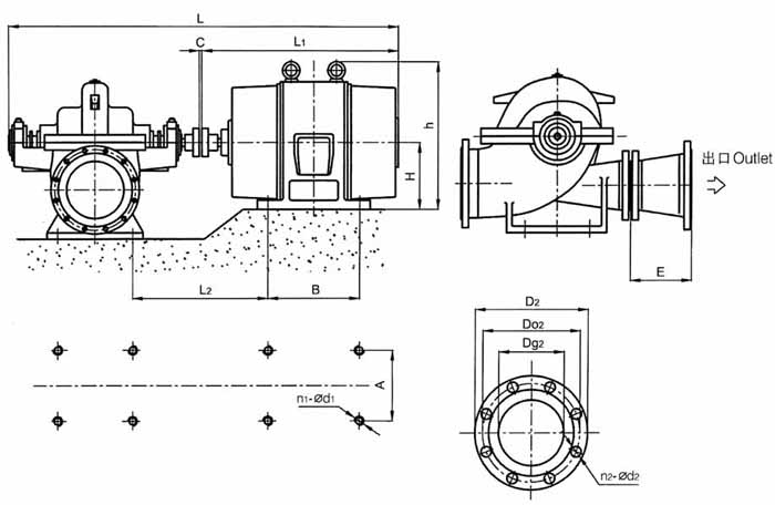
安装尺寸图(不带底座):
The drawing for the installation dimensions (without bedplate):
Assembly and disassembly
(Please use the following procedures to assemble)
1.Assemble keys. Impeller sleeves, sleeve nuts packing rings, and block water ring in order on the pump shaft. Afterwards sleeve the suction seal ring, and then the bearing part and coupling.
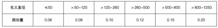
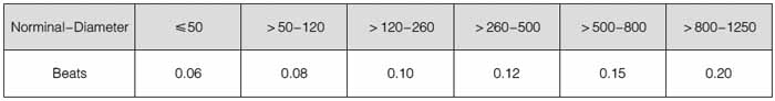
2.Individully inspect the radial beats of the excircle of the impeller seal position and the sleeve excircle on the rotor part, which is not allowed to exceed its provisions as following:
3.Assemble the rotor part and studs on the pump casing, and well install the bearing gland and tighten it with bolls, then you can adjust the axial position of the impeller with shaft sleeve nuts up to middle flow passage way of the pump casing and tighten it.
4.Feed the packing into the packing box. Place the horizental joint paper gasket, cover the pump, hammar(or other things) the taper pin with external thread tightly, the following, screw its nuts and mount the packing gland which degree of the packing tightness must be suitbale(if too light, the shaft sleeve would be over heated, samely more power would be consumed; if too loose, the leakage of liquid would be found from here, and thus would decrease the pump efficiency.)
5.After finish assembling the pump, tum the rotor with hands, it should be fiexible and smooth as well as no block and no rubbing, that is OK! And then you can operate it freely.
(Disassemble it according to the opposite order of assembling)
Installation
1.Check whether the pump and the motor are in good condition.
2.Make sure that the value of NPSH must be higher than the one that have been given, and ist foundation dimensions should be in comformity with the installation drawing.
3.The steps of installation:
(1)Sleeve the foot bolts and hat the nuts on the pump and the motor, place the pump on the concret foundation where some foot bolt holes are pre=built, correct the horizental and the coaxial degree between the pump shaft and the motor shaft by means of adjusting the wedge=shaped cushion, then fully pour the concrete into all the foot bolt holes.
(2)After the concret solidifed, again correct the coaxial degree in the excircle of the two couplings, the error of the correction is not more that 0.1mm, the allowable error of the inhomogeneous degree of the endface clearance along the circle is 0.3mm, Re-inspect the correct precision after tightening the foot nuts, finally, pour concrete fully under the foot of the pump and the motor except the around of the wedge shaped cushion.
(3)After check the rotary direction of the motor which is now in keeping with that of the pump, you can install the connecting parallel pin of the coupling.
4.The inlet pipe and outlet pipe should be supported by a brasket instead of the pump casing.
5.The combination between the pump and the pipe must be keeping good sealing, especially no leakage of air occures from the inlet pipe and no possible remained air in it in the cause of installation.
6.If the pump is installed above the suction water level, it should be equiped foot valve for pouring water and driving and it also can suck water by suction vacuum.
Above all the mentioned methods and requirements are suitable for the pump set without common bedplate; samely, for the pump set with common bedplate, you also can refer to the above mention methods.
Starting stopping and running
Starting and stopping:
1.Before starting, turning the rotor, it should be flexible.
2.Close the discharge valve, pour water in it (if no foot valve, with a vacuum pump for drawing water instead ). Be sure the pump full of water and no air remained in it.
3.If there is a vacuum gauge installed on the pump, the cocks on the pipe passage way which connect the pump should be turned off. Then start the motor. It is not allowed to turn on the motor until the running speed is normal, and then open gradully the brake valve untill the suction water of the two sides reach to balance.
4.Screw equably the nuts on the pump packing gland so as to the leakage of liquid is in small quantity, at the same time, pay more attention to the packing case temperature rising.
5.While stopping the pump ruing, first tum off the cocks of the vacuum gauge and manometer and tum off the brake valve on the discharge pipe passage way. If the ambient temperature is low, the coach under the pump casing should be loosen to drain away the rest water so as to keep the pump casing from being split by forst.
6.If it will not be used for a long time, the pump must be disconnected and all the parts should be kept dry, and smear the machining face with rust=proof grease oil.
R unning:
1.The temperature of the pump bearing should not be exceeded 75℃.
2.The suitable quantity of calcium grease which is used to lubricate the bearing occupies 1/3 to 1/2space of the bearing body, and it should be changed periodically.
3.When the paking worn, tighten the packing gland properly or change it if necessary.
4.Check the flexible coupling part, care more for the motor bearing temperature rising.
5.During running, if any noise or unnormal sounds are heard, stop the pump immediately, and look for the causes, then clear out.
6.It is not allowed to increase the running speed at will, but you can decrease the running speed of the pump for working.
")